With
most of the body completed it was now time to do some fine tuning to the
steering and throttle. Steering adjustments were relatively straight forward, I
wanted there to be a dead zone where the car could go straight even with the
bike not being in perfect center. In order to achieve this I put in some simple
logic to the code:
Showing posts with label Virtual Reality R/C Car. Show all posts
Showing posts with label Virtual Reality R/C Car. Show all posts

RC Car Project - Update 2
Whew! Another long time since an update on the RC Car project!
There have been some major developments on the project since last time and I’ll go through them here.
After the last update, I did design a PCB to condense the project into a neater form factor, however there were several issues with the design and ultimately the board was nonfunctional. After spending a few days attempting to get the board working correctly I made the decision to put that on hold and get the car working again (it was dissembled for parts). This was supposed to be a simple task considering I had done it once but after several days of work I was left unable to make the radio modules communicate with each other. It was at this point I decided to move the system to a new platform.
There have been some major developments on the project since last time and I’ll go through them here.
After the last update, I did design a PCB to condense the project into a neater form factor, however there were several issues with the design and ultimately the board was nonfunctional. After spending a few days attempting to get the board working correctly I made the decision to put that on hold and get the car working again (it was dissembled for parts). This was supposed to be a simple task considering I had done it once but after several days of work I was left unable to make the radio modules communicate with each other. It was at this point I decided to move the system to a new platform.
RC Car Project Update
It’s been a long time since anyone has worked on the RC Car project here in the Workshop and since I’m new to this project I figured now is a great time to begin simplifying and streamlining the wiring. The way everything was wired previously was great for prototyping but it left something to be desired for a more polished product. A lot of the wiring had gotten messed up from moving the bikes and just leaving the project unused for so long, so I grabbed a multimeter and began the work by checking all the connections. Previously a breadboard was used to send power to the bikes and also serve as a hub point to read the data from. This created a mess of wires that made it difficult to see how things connect and so I soldered up all the power lines and ground lines and added on a male pin. Now they can be directly connected to the 5v and GND pins on the Arduino itself. I then added male pins to each of the three signal wires so that they too could be plugged directly into the Arduino. With this new setup, I could eliminate the breadboard which cleaned up things nicely. Now that the connections were simplified I verified that everything was working and turned my attention to the RC car itself. When I began working on the car nothing seemed to be responsive. So, I decided to dissemble the system and redo it, following the same guidelines used previously, which fixed the issues. Now both Arduinos are communicating correctly and everything seems to be working except for the throttle which is glitchy at best. Once the receiver side is fully functional I’ll streamline the wiring and clean it up. Things on the to-do list for this project now are:
- Fix Throttle response
- Clean wiring on receiver side
- Add buttons to enable reverse mode
- Reimplement the FPV system
Once all these are done I’ll be designing a PCB that will condense everything and make the project more professional. Below you’ll find the current versions of the code being used on the project.
-Andrew
Virtual Reality R/C Car: Part 5
There are a couple of parts of this project that I am currently trying to tie together but am not quite there yet on each of them. The three things that I have been working on are running the Atmega328P micro-controller without the jump board, changing the R/C Car being used, and integrating the head tracker with the rest of the project.


Changing out the R/C cars has actually been in the making for some time now. The 3D printed truggy had been in the shop when I got here but was not functional. The first issue that I had while working on this car was the differential gears that were make out of PLA the mesh was tough to get right and I had some problems with parts breaking. To fix this I decided to order metal parts for the drive train. I got this idea from a great thing on thingiverse here is the link:
I printed the extra parts, mainly the pinion and spur gears, out of Hatchbox PLA. Soon after the car got a new set of electronics. The motor and ESC that I am currently using are the Traxxas Titan 12T DC motor and the Traxxas XL-5 electronic speed controller. This set up worked temporarily but the spur and pinion gear failed quickly here is a video of the test below.
Since they failed so quickly I decided to try ABS instead. Here is a picture of the new spur and pinion set up.

And here is a picture of the new center differential. These gears should be able to hold up much longer than their PLA counterparts. However some part of the drive-train seems to be sticking. I still need to investigate this issue further.
The next part of this project that I want to talk about is running the Atmega328P chip without the Arduino board. This is what will allow for a printed circuit board to be made for the receiver and transmitter in the future along. This should make the entire design more sleek and durable long term. To do this I started out following the tutorial for using the Atmega328P chip standalone found on Arduinos website. Here is a link:
This is basically a way to run the micro-controller on a breadboard by itself while using the arduino only as a power source and FTDI programmer. The tutorial also explains how to burn the bootloader using the ArduinoISP to burn the firmware. This process allows the chip to understand the code that you write in the Arduino IDE on your computer and upload to it. However, this tutorial did not work for me. I was double and triple checking my wires but nothing seemed to work. In the tutorial it says to select either the Nano or Duemilanova board and then select the Atmega328P option. While doing this the IDE would try to upload the code but eventually time out while trying to connect to the chip. The way that I fixed this was by selecting the Uno/Genuino as the board and then uploading as usual. I am not sure if the tutorial is just wrong or if the board selection that they recommend would work if you also flashed the bootloader using the ArduinoISP. Here is a picture of the working set up.

In this picture I was just testing to make sure I could upload code to the chip and turn on an LED. This will eventually just be the power LED on the board. The connections to the board are Tx and Rx for programming and 5V and GND to power the chip.
After I figured this out the next move was to prototype the entire system on a breadboard and have it run totally independently. While doing this I also want to integrate the head tracker and pan/tilt/roll camera mount. I have most of the receiver and transmitter wired on a breadboard here are pictures of the two.
Receiver Circuit

Transmitter Circuit

I still need to rework the code before testing these two circuit. The main three changes that need to be made are adding one part of the IMU code to the transmitter, the other part to the receiver, and redo all the pin numbers in the code. The reason i have to redo all the pin numbers is because the pins on the standalone chip do not exactly match up with the software. The way that I tell which pin is which is this diagram:

This diagram is really a lifesaver when it comes to working with the UNO it lets you easily see the multiple uses of each pin.
Virtual Reality R/C Car: Part 4 Adding The Head Tracker
After some testing, we realized that only looking forward is very limiting. Almost everyone who drove the car was tilting their head one way or another in order to try and look around. After doing a little more research on Fatshark's Trinity Head tracking Module I realized that it would be easier to just use another IMU. This was because the trinity is meant to be used with one of the store/online bought R/C remote controllers. However I did order a roll, pan, and tilt camera mount for the FatShark 700L CMOS V2 Camera you can find it here:
http://www.getfpv.com/fatshark-pan-tilt-roll-camera-mount-servos.html?utm_source=google_shopping&m=simple&gdffi=747627bc7e464db68e5f529d971aacf3&gdfms=5072B314B330484BA513E58972DCB359&gclid=CKGevMjpos4CFQsehgodZjQPjA
After looking around online for a bit I chose to use Adafruit's 9DOF IMU Breakout board. You can find it here:
https://www.adafruit.com/product/1714
Adafruit has lots of documentation on all their boards and that makes it much easier to use their products. Once we got the board the next step was to get it hooked up and to learn how it worked. Some information about how to connect the board can be found here:
https://learn.adafruit.com/adafruit-9-dof-imu-breakout/connecting-it-up
Basically what that page translates to is this:
Arduino IMU
5V <<-->> Vin
GND <<-->> GND
A5 <<-->> SCL
A4 <<-->> SDA
Also I connected pins 3, 5, and 6 to the signal pins of the pan, tilt, and roll Servos on the camera mount.
After I connected everything up it was time to start downloading libraries and putting the test code together. I found all my information on how to set up the code for this chip from here:
https://learn.adafruit.com/adafruit-9-dof-imu-breakout/software
The key thing is that you have successfully downloaded all four of the libraries they mention in the articles above. The LSM303DLHC and L3DG20 libraries are there to read the information from the gyro and accelerometer/magnetometer. The unified sensor library combines all of this information and the 9DOF library makes this information extremely easy to interpret. On Adafruit's Github they even have an example sketch to help get you started which I have adapted to print some more debugging information and to control the servos. This code that I used to test both the IMU and the camera mount can be found on my Github here:
https://github.com/lukebocabearings/VRRC/blob/master/IMU_TEST
And a video of the code in action:
So now that I know how to use the IMU to control the camera mount the next step will be to add the IMU to the board to the transmitting Arduino connected to arcade motorcycle and to add the camera mount to the receiving Arduino on the car. Also I want to make the step towards running the ATMEGA328p micro-controllers totally separate for the Arduino boards. This will help make the wiring cleaner, the design more durable, and also with the help of CircuitMaker (a PCB design software) the design easier for anyone to recreate. Here are the schematics that I have drawn up to include the IMU and servos for the camera mount.


http://www.getfpv.com/fatshark-pan-tilt-roll-camera-mount-servos.html?utm_source=google_shopping&m=simple&gdffi=747627bc7e464db68e5f529d971aacf3&gdfms=5072B314B330484BA513E58972DCB359&gclid=CKGevMjpos4CFQsehgodZjQPjA
After looking around online for a bit I chose to use Adafruit's 9DOF IMU Breakout board. You can find it here:
https://www.adafruit.com/product/1714
Adafruit has lots of documentation on all their boards and that makes it much easier to use their products. Once we got the board the next step was to get it hooked up and to learn how it worked. Some information about how to connect the board can be found here:
https://learn.adafruit.com/adafruit-9-dof-imu-breakout/connecting-it-up
Basically what that page translates to is this:
Arduino IMU
5V <<-->> Vin
GND <<-->> GND
A5 <<-->> SCL
A4 <<-->> SDA
Also I connected pins 3, 5, and 6 to the signal pins of the pan, tilt, and roll Servos on the camera mount.
After I connected everything up it was time to start downloading libraries and putting the test code together. I found all my information on how to set up the code for this chip from here:
https://learn.adafruit.com/adafruit-9-dof-imu-breakout/software
The key thing is that you have successfully downloaded all four of the libraries they mention in the articles above. The LSM303DLHC and L3DG20 libraries are there to read the information from the gyro and accelerometer/magnetometer. The unified sensor library combines all of this information and the 9DOF library makes this information extremely easy to interpret. On Adafruit's Github they even have an example sketch to help get you started which I have adapted to print some more debugging information and to control the servos. This code that I used to test both the IMU and the camera mount can be found on my Github here:
https://github.com/lukebocabearings/VRRC/blob/master/IMU_TEST
And a video of the code in action:
So now that I know how to use the IMU to control the camera mount the next step will be to add the IMU to the board to the transmitting Arduino connected to arcade motorcycle and to add the camera mount to the receiving Arduino on the car. Also I want to make the step towards running the ATMEGA328p micro-controllers totally separate for the Arduino boards. This will help make the wiring cleaner, the design more durable, and also with the help of CircuitMaker (a PCB design software) the design easier for anyone to recreate. Here are the schematics that I have drawn up to include the IMU and servos for the camera mount.
Receiver Diagram

Transmitter Diagram

Virtual Reality R/C Car Part 3
So the next step on this project is really what sets this project apart from your typical R/C build. In order to make the driver feel like they are actually driving the car we added a FatShark FPV system to the car. In order to mount this system on the car I created a self contained box for the radio receiver, small LiPo battery, and the FatShark camera. If you have a 3D printer and a FatShark set up at home here is a link to the STL Files:
http://www.thingiverse.com/thing:1683678
Here is the case assembled and mounted on the car:

To put the case together I used 4 2.5mm screws and two #10 x 5/8 screw and nuts. I purchased the on/off switch from amazon at this link:
https://www.amazon.com/Yueton-Blovess-Rocker-Toggle-Control/dp/B011U1NU90?ie=UTF8&*Version*=1&*entries*=0
The goggles that we are using for the system are the FatShark Teleporter Model. Which work pretty well. The main drawback of the setup currently is that the camera is fixed facing forward on the car. While driving you want to be able to look around. Its kind of like trying to drive a car that only has a windshield. It works but it does not feel totally intuitive. In the future I would like to add some sort of moving camera mount that follows the head motion of the driver. Either with an accelerometer, two servos, and an Arduino or with some technology from FatShark. I know FatShark makes a Trinity Head Tracker Module so this may be a good route to go.
Also I have made a slight change to the code as well. The car now has two modes determined by the position of a switch. There is Easy Mode (Shown above) and Sport Mode. The difference is in easy mode the cars speed is limited. However in sport mode the more you turn the throttle the faster the car will go. It is harder to control that way but once you get used to it, it is very worth it. I will post a video soon of a test of this change. I have Highlighted the changes I made in the code to do this below:
#include <SoftwareServo.h>
#include <SPI.h>
#include "RF24.h"
RF24 radio(9, 10);
SoftwareServo steering;
SoftwareServo gogojuice;
byte addresses[][6] = {"1Node", "2Node"}; // These will be the names of the "Pipes"
struct dataStruct {
unsigned long _micros; // to save response times
int throttle; // The Joystick position values
int handBreak;
int bikeTilt;
bool pushButton; // The Joystick push-down switch
} myData; // This can be accessed in the form: myData.Xposition etc.
void setup()
{
Serial.begin(115200);
pinMode(6,INPUT);
pinMode(3, OUTPUT);
pinMode(5, OUTPUT);
radio.begin(); // Initialize the nRF24L01 Radio
radio.setChannel(108);
radio.setDataRate(RF24_250KBPS);
radio.setPALevel(RF24_PA_HIGH);
// Open a writing and reading pipe on each radio, with opposite addresses
radio.openWritingPipe(addresses[1]);
radio.openReadingPipe(1, addresses[0]);
// Start the radio listening for data
radio.startListening();
steering.attach(3);
gogojuice.attach(5);
gogojuice.write(40);
}
void loop()
{
if ( radio.available())
{
while (radio.available()) // While there is data ready to be retrieved from the receive pipe
{
radio.read( &myData, sizeof(myData) ); // Get the data
}
radio.stopListening(); // First stop listening so we can transmit
radio.write( &myData, sizeof(myData) ); // Send the received data back.
radio.startListening(); // Now resume listening so we catch the next packet
}
double Mode;
if (HIGH == digitalRead(6))
{
Mode = 0.01;
}
else
{
Mode = 0;
}
SoftwareServo::refresh();
int drive;
int bikeTiltRecieved = myData.bikeTilt;
int handBreakRecieved = myData.handBreak;
int throttleRecieved = myData.throttle;
int tilt = map(bikeTiltRecieved, 0, 1023, 0, 180);
if (throttleRecieved > 100 && handBreakRecieved < 100)
{
drive = 96 + throttleRecieved*Mode;
}
if (throttleRecieved < 100 && handBreakRecieved > 100)
{
drive = 85;
}
if (throttleRecieved > 100 && handBreakRecieved > 100)
{
drive = 90;
}
if (throttleRecieved < 100 && handBreakRecieved < 100)
{
drive = 90;
}
steering.write(tilt);
gogojuice.write(drive);
Serial.println(drive);
}
http://www.thingiverse.com/thing:1683678
Here is the case assembled and mounted on the car:

To put the case together I used 4 2.5mm screws and two #10 x 5/8 screw and nuts. I purchased the on/off switch from amazon at this link:
https://www.amazon.com/Yueton-Blovess-Rocker-Toggle-Control/dp/B011U1NU90?ie=UTF8&*Version*=1&*entries*=0
The goggles that we are using for the system are the FatShark Teleporter Model. Which work pretty well. The main drawback of the setup currently is that the camera is fixed facing forward on the car. While driving you want to be able to look around. Its kind of like trying to drive a car that only has a windshield. It works but it does not feel totally intuitive. In the future I would like to add some sort of moving camera mount that follows the head motion of the driver. Either with an accelerometer, two servos, and an Arduino or with some technology from FatShark. I know FatShark makes a Trinity Head Tracker Module so this may be a good route to go.
Also I have made a slight change to the code as well. The car now has two modes determined by the position of a switch. There is Easy Mode (Shown above) and Sport Mode. The difference is in easy mode the cars speed is limited. However in sport mode the more you turn the throttle the faster the car will go. It is harder to control that way but once you get used to it, it is very worth it. I will post a video soon of a test of this change. I have Highlighted the changes I made in the code to do this below:
#include <SoftwareServo.h>
#include <SPI.h>
#include "RF24.h"
RF24 radio(9, 10);
SoftwareServo steering;
SoftwareServo gogojuice;
byte addresses[][6] = {"1Node", "2Node"}; // These will be the names of the "Pipes"
struct dataStruct {
unsigned long _micros; // to save response times
int throttle; // The Joystick position values
int handBreak;
int bikeTilt;
bool pushButton; // The Joystick push-down switch
} myData; // This can be accessed in the form: myData.Xposition etc.
void setup()
{
Serial.begin(115200);
pinMode(6,INPUT);
pinMode(3, OUTPUT);
pinMode(5, OUTPUT);
radio.begin(); // Initialize the nRF24L01 Radio
radio.setChannel(108);
radio.setDataRate(RF24_250KBPS);
radio.setPALevel(RF24_PA_HIGH);
// Open a writing and reading pipe on each radio, with opposite addresses
radio.openWritingPipe(addresses[1]);
radio.openReadingPipe(1, addresses[0]);
// Start the radio listening for data
radio.startListening();
steering.attach(3);
gogojuice.attach(5);
gogojuice.write(40);
}
void loop()
{
if ( radio.available())
{
while (radio.available()) // While there is data ready to be retrieved from the receive pipe
{
radio.read( &myData, sizeof(myData) ); // Get the data
}
radio.stopListening(); // First stop listening so we can transmit
radio.write( &myData, sizeof(myData) ); // Send the received data back.
radio.startListening(); // Now resume listening so we catch the next packet
}
double Mode;
if (HIGH == digitalRead(6))
{
Mode = 0.01;
}
else
{
Mode = 0;
}
SoftwareServo::refresh();
int drive;
int bikeTiltRecieved = myData.bikeTilt;
int handBreakRecieved = myData.handBreak;
int throttleRecieved = myData.throttle;
int tilt = map(bikeTiltRecieved, 0, 1023, 0, 180);
if (throttleRecieved > 100 && handBreakRecieved < 100)
{
drive = 96 + throttleRecieved*Mode;
}
if (throttleRecieved < 100 && handBreakRecieved > 100)
{
drive = 85;
}
if (throttleRecieved > 100 && handBreakRecieved > 100)
{
drive = 90;
}
if (throttleRecieved < 100 && handBreakRecieved < 100)
{
drive = 90;
}
steering.write(tilt);
gogojuice.write(drive);
Serial.println(drive);
}
Virtual Reality R/C Car Part 2
Now that I know the values that each of the potentiometers on the bike output, the next step is to transmit the values over a radio. The Arduino compatible Radio Frequency chips that I chose to use were the nRF24L01+ 2.4GHz wireless transceivers. I chose these transceivers for a couple reasons. One is that these chips is that they come in two different models that communicate with the the Arduino the same way. The low power version comes with a built in antenna and has a range of about 100 feet. I have seen this model vary in price from $0.89 to around $4. The high power version has an external antenna and has a range of around 1000 feet. I have seen this model vary in price from about $4 to $15 online.
Low Power Module

High Power Module

Another reason I chose to use these modules was because they are well documented and widely used. I suppose they are so widely used because of how inexpensive they are. But all the documentation I used to learn how to set them up can be found here:
https://arduino-info.wikispaces.com/Nrf24L01-2.4GHz-HowTo
This website gives some great examples and background knowledge of how the chips work so that anyone can begin transmitting radio signals in no time. One thing that needs to be added to the chip though is a capacitor across power and ground. Without this capacitor the chip will not function properly. The capacitor should be between 3.3 and 10 micro Farads. An example shown below.

So the next step to getting this bike working as a R/C car controller was to make sure that the Arduino connected to the bike potentiometers would use the nRF24L01+ to transmit the values and another Arduino which would use it's own nRF24L01+ to read these values and print them to the serial monitor on the computer screen to check that they are in fact the same ranges of values that were read before.
Connecting the nRFL01+

The library that I used to interface the Arduino with the chip was the TMRh20 RF24 library so I used the fifth column to determine where to hook up each pin. This makes it really easy to connect and use the chips because once the TMRh20 RF24 library is downloaded and included, the functions created in this library can be used to interface with the chip. Below is the Code I used to test the chips and make sure that the data made it from one chip to the next.
Transmit Code
#include <SPI.h> //SPI library to communicate with the nRF24+
#include "RF24.h" //
#include "printf.h" // Needed for "printDetails" which is a debugging tool
#define CE_PIN 9 // The pins to be used for CE and CSN
#define CSN_PIN 10
RF24 radio(CE_PIN, CSN_PIN);
byte addresses[][6] = {"1Node", "2Node"}; // These will be the names of the "Pipes"
unsigned long timeNow; // Used to grab the current time, calculate delays
unsigned long started_waiting_at;
boolean timeout; // Timeout? True or False
struct dataStruct {
unsigned long _micros; // to save response times
int throttle; // The Joystick position values
int handBreak;
int bikeTilt;
} myData; // This can be accessed in the form: myData.throttle
void setup()
{
Serial.begin(115200); //Baud Rate
/*printf_begin(); //uncomment for debug info*/
radio.begin(); // Initialize the nRF24L01 Radio
radio.setChannel(108); // Above most WiFi frequencies corresponds to 2.400 GHz + 0.108 GHz meaning radio is set to 2.508 GHz
radio.setDataRate(RF24_250KBPS);
//radio.setPALevel(RF24_PA_LOW);
radio.setPALevel(RF24_PA_HIGH);
// radio.setPALevel(RF24_PA_MAX);
// Open a writing and reading pipe on each radio, with opposite addresses
radio.openWritingPipe(addresses[0]);
radio.openReadingPipe(1, addresses[1]);
// Start the radio listening for data
radio.startListening();
// radio.printDetails(); //Uncomment to show a ton of debugging information
}
void loop() /****** LOOP: RUNS CONSTANTLY ******/
{
radio.stopListening(); // First, stop listening so we can talk.
myData.throttle = analogRead(A0);
myData.handBreak = analogRead(A2);
myData.bikeTilt = analogRead(A4);
myData.pushButton = digitalRead(7); // Invert the pulldown switch
myData._micros = micros(); // Send back for timing
Serial.print("Throttle = ");
Serial.print(myData.throttle);
Serial.print("\t");
Serial.print("Hand Break = ");
Serial.print(myData.handBreak);
Serial.print("\t");
Serial.print("Bike Tilt = ");
Serial.println(myData.bikeTilt);
// Serial.print(F("Now sending - "));
if (!radio.write( &myData, sizeof(myData) )) {
Serial.println(F("Transmit failed "));
}
radio.startListening();
started_waiting_at = micros(); // timeout period, get the current microseconds
timeout = false; // variable to indicate if a response was received or not
while ( ! radio.available() ) {
if (micros() - started_waiting_at > 200000 ) { // If waited longer than 200ms, indicate timeout and exit while loop
timeout = true;
break;
}
}
if ( timeout )
{ // Describe the results
Serial.println(F("Response timed out - no Acknowledge."));
}
else
{
// Grab the response, compare, and send to Serial Monitor
radio.read( &myData, sizeof(myData) );
timeNow = micros();
// Show it
/*
Serial.print(F("Sent "));
Serial.print(timeNow);
Serial.print(F(", Got response "));
Serial.print(myData._micros);
Serial.print(F(", Round-trip delay "));
Serial.print(timeNow - myData._micros);
Serial.println(F(" microseconds "));
*/
}
// Send again after delay. When working OK, change to something like 100
delay(100);
}
Receive Code
#include <SPI.h>
#include "RF24.h"
RF24 radio(9, 10);
byte addresses[][6] = {"1Node", "2Node"}; // These will be the names of the "Pipes"
struct dataStruct {
unsigned long _micros; // to save response times
int throttle; // The Joystick position values
int handBreak;
int bikeTilt;
} myData; // This can be accessed in the form: myData.throttle
void setup()
{
Serial.begin(115200);
radio.begin(); // Initialize the nRF24L01 Radio
radio.setChannel(108); //make sure it is the same channel as the tranmitter
radio.setDataRate(RF24_250KBPS);
radio.setPALevel(RF24_PA_HIGH);
// Open a writing and reading pipe on each radio, with opposite addresses
radio.openWritingPipe(addresses[1]);
radio.openReadingPipe(1, addresses[0]);
// Start the radio listening for data
radio.startListening();
}
void loop()
{
if ( radio.available())
{
while (radio.available()) // While there is data ready to be retrieved from the receive pipe
{
radio.read( &myData, sizeof(myData) ); // Get the data
}
radio.stopListening(); // First stop listening so we can transmit
radio.write( &myData, sizeof(myData) ); // Send the received data back.
radio.startListening(); // Now resume listening so we catch the next packet
Serial.print("Throttle = ");
Serial.print(myData.throttle);
Serial.print("\t");
Serial.print("Hand Break = ");
Serial.print(myData.handBreak);
Serial.print("\t");
Serial.print("Bike Tilt = ");
Serial.println(myData.bikeTilt);
}
}
Now that we know the radio chips are communicating properly the next step is to make sure that the receiving Arduino can use the data it receives to control both the ESC and the Servo on the R/C car. To do this I have updated the code on the receiving Arduino a little bit.
The ESC can be controlled the same as a servo but because the regular <Servo.h> has a timer conflict with the RF24 library the <SoftwareServo.h> library was implemented. This library works very similar to the regular servo library. The main difference is that the SoftwareServo::refresh(); function must be called each loop in order to update the value being written to the servo. Another intricacy of using the Arduino to power the ESC is that it must be "primed." This means that it needs an initial value to be written to it before it is actually responsive.
Code
#include <SoftwareServo.h>
#include <SPI.h>
#include "RF24.h"
RF24 radio(9, 10);
SoftwareServo steering;
SoftwareServo ESC;
byte addresses[][6] = {"1Node", "2Node"}; // These will be the names of the "Pipes"
struct dataStruct {
unsigned long _micros; // to save response times
int throttle; // The Joystick position values
int handBreak;
int bikeTilt;
} myData; // This can be accessed in the form: myData.Xposition etc.
void setup()
{
Serial.begin(115200);
pinMode(3, OUTPUT);
pinMode(5, OUTPUT);
radio.begin(); // Initialize the nRF24L01 Radio
radio.setChannel(108);
radio.setDataRate(RF24_250KBPS);
radio.setPALevel(RF24_PA_HIGH);
// Open a writing and reading pipe on each radio, with opposite addresses
radio.openWritingPipe(addresses[1]);
radio.openReadingPipe(1, addresses[0]);
// Start the radio listening for data
radio.startListening();
steering.attach(3);
ESC.attach(5);
ESC.write(40); //to prime the ESC
}
void loop()
{
if ( radio.available())
{
while (radio.available()) // While there is data ready to be retrieved from the receive pipe
{
radio.read( &myData, sizeof(myData) ); // Get the data
}
radio.stopListening(); // First stop listening so we can transmit
radio.write( &myData, sizeof(myData) ); // Send the received data back.
radio.startListening(); // Now resume listening so we catch the next packet
}
SoftwareServo::refresh();
int drive;
int bikeTiltRecieved = myData.bikeTilt;
int handBreakRecieved = myData.handBreak;
int throttleRecieved = myData.throttle;
int tilt = map(bikeTiltRecieved, 0, 1023, 0, 180);
if (throttleRecieved > 100 && handBreakRecieved < 100)
{
drive = 96;
}
if (throttleRecieved < 100 && handBreakRecieved > 100)
{
drive = 85;
}
if (throttleRecieved > 100 && handBreakRecieved > 100)
{
drive = 90;
}
if (throttleRecieved < 100 && handBreakRecieved < 100)
{
drive = 90;
}
steering.write(tilt);
ESC.write(drive);
Serial.println(drive);
}
Low Power Module
High Power Module
Another reason I chose to use these modules was because they are well documented and widely used. I suppose they are so widely used because of how inexpensive they are. But all the documentation I used to learn how to set them up can be found here:
https://arduino-info.wikispaces.com/Nrf24L01-2.4GHz-HowTo
This website gives some great examples and background knowledge of how the chips work so that anyone can begin transmitting radio signals in no time. One thing that needs to be added to the chip though is a capacitor across power and ground. Without this capacitor the chip will not function properly. The capacitor should be between 3.3 and 10 micro Farads. An example shown below.

So the next step to getting this bike working as a R/C car controller was to make sure that the Arduino connected to the bike potentiometers would use the nRF24L01+ to transmit the values and another Arduino which would use it's own nRF24L01+ to read these values and print them to the serial monitor on the computer screen to check that they are in fact the same ranges of values that were read before.
Connecting the nRFL01+

The library that I used to interface the Arduino with the chip was the TMRh20 RF24 library so I used the fifth column to determine where to hook up each pin. This makes it really easy to connect and use the chips because once the TMRh20 RF24 library is downloaded and included, the functions created in this library can be used to interface with the chip. Below is the Code I used to test the chips and make sure that the data made it from one chip to the next.
Transmit Code
#include <SPI.h> //SPI library to communicate with the nRF24+
#include "RF24.h" //
#include "printf.h" // Needed for "printDetails" which is a debugging tool
#define CE_PIN 9 // The pins to be used for CE and CSN
#define CSN_PIN 10
RF24 radio(CE_PIN, CSN_PIN);
byte addresses[][6] = {"1Node", "2Node"}; // These will be the names of the "Pipes"
unsigned long timeNow; // Used to grab the current time, calculate delays
unsigned long started_waiting_at;
boolean timeout; // Timeout? True or False
struct dataStruct {
unsigned long _micros; // to save response times
int throttle; // The Joystick position values
int handBreak;
int bikeTilt;
} myData; // This can be accessed in the form: myData.throttle
void setup()
{
Serial.begin(115200); //Baud Rate
/*printf_begin(); //uncomment for debug info*/
radio.begin(); // Initialize the nRF24L01 Radio
radio.setChannel(108); // Above most WiFi frequencies corresponds to 2.400 GHz + 0.108 GHz meaning radio is set to 2.508 GHz
radio.setDataRate(RF24_250KBPS);
//radio.setPALevel(RF24_PA_LOW);
radio.setPALevel(RF24_PA_HIGH);
// radio.setPALevel(RF24_PA_MAX);
// Open a writing and reading pipe on each radio, with opposite addresses
radio.openWritingPipe(addresses[0]);
radio.openReadingPipe(1, addresses[1]);
// Start the radio listening for data
radio.startListening();
// radio.printDetails(); //Uncomment to show a ton of debugging information
}
void loop() /****** LOOP: RUNS CONSTANTLY ******/
{
radio.stopListening(); // First, stop listening so we can talk.
myData.throttle = analogRead(A0);
myData.handBreak = analogRead(A2);
myData.bikeTilt = analogRead(A4);
myData.pushButton = digitalRead(7); // Invert the pulldown switch
myData._micros = micros(); // Send back for timing
Serial.print("Throttle = ");
Serial.print(myData.throttle);
Serial.print("\t");
Serial.print("Hand Break = ");
Serial.print(myData.handBreak);
Serial.print("\t");
Serial.print("Bike Tilt = ");
Serial.println(myData.bikeTilt);
// Serial.print(F("Now sending - "));
if (!radio.write( &myData, sizeof(myData) )) {
Serial.println(F("Transmit failed "));
}
radio.startListening();
started_waiting_at = micros(); // timeout period, get the current microseconds
timeout = false; // variable to indicate if a response was received or not
while ( ! radio.available() ) {
if (micros() - started_waiting_at > 200000 ) { // If waited longer than 200ms, indicate timeout and exit while loop
timeout = true;
break;
}
}
if ( timeout )
{ // Describe the results
Serial.println(F("Response timed out - no Acknowledge."));
}
else
{
// Grab the response, compare, and send to Serial Monitor
radio.read( &myData, sizeof(myData) );
timeNow = micros();
// Show it
/*
Serial.print(F("Sent "));
Serial.print(timeNow);
Serial.print(F(", Got response "));
Serial.print(myData._micros);
Serial.print(F(", Round-trip delay "));
Serial.print(timeNow - myData._micros);
Serial.println(F(" microseconds "));
*/
}
// Send again after delay. When working OK, change to something like 100
delay(100);
}
Receive Code
#include <SPI.h>
#include "RF24.h"
RF24 radio(9, 10);
byte addresses[][6] = {"1Node", "2Node"}; // These will be the names of the "Pipes"
struct dataStruct {
unsigned long _micros; // to save response times
int throttle; // The Joystick position values
int handBreak;
int bikeTilt;
} myData; // This can be accessed in the form: myData.throttle
void setup()
{
Serial.begin(115200);
radio.begin(); // Initialize the nRF24L01 Radio
radio.setChannel(108); //make sure it is the same channel as the tranmitter
radio.setDataRate(RF24_250KBPS);
radio.setPALevel(RF24_PA_HIGH);
// Open a writing and reading pipe on each radio, with opposite addresses
radio.openWritingPipe(addresses[1]);
radio.openReadingPipe(1, addresses[0]);
// Start the radio listening for data
radio.startListening();
}
void loop()
{
if ( radio.available())
{
while (radio.available()) // While there is data ready to be retrieved from the receive pipe
{
radio.read( &myData, sizeof(myData) ); // Get the data
}
radio.stopListening(); // First stop listening so we can transmit
radio.write( &myData, sizeof(myData) ); // Send the received data back.
radio.startListening(); // Now resume listening so we catch the next packet
Serial.print("Throttle = ");
Serial.print(myData.throttle);
Serial.print("\t");
Serial.print("Hand Break = ");
Serial.print(myData.handBreak);
Serial.print("\t");
Serial.print("Bike Tilt = ");
Serial.println(myData.bikeTilt);
}
}
Now that we know the radio chips are communicating properly the next step is to make sure that the receiving Arduino can use the data it receives to control both the ESC and the Servo on the R/C car. To do this I have updated the code on the receiving Arduino a little bit.
The ESC can be controlled the same as a servo but because the regular <Servo.h> has a timer conflict with the RF24 library the <SoftwareServo.h> library was implemented. This library works very similar to the regular servo library. The main difference is that the SoftwareServo::refresh(); function must be called each loop in order to update the value being written to the servo. Another intricacy of using the Arduino to power the ESC is that it must be "primed." This means that it needs an initial value to be written to it before it is actually responsive.
Code
#include <SoftwareServo.h>
#include <SPI.h>
#include "RF24.h"
RF24 radio(9, 10);
SoftwareServo steering;
SoftwareServo ESC;
byte addresses[][6] = {"1Node", "2Node"}; // These will be the names of the "Pipes"
struct dataStruct {
unsigned long _micros; // to save response times
int throttle; // The Joystick position values
int handBreak;
int bikeTilt;
} myData; // This can be accessed in the form: myData.Xposition etc.
void setup()
{
Serial.begin(115200);
pinMode(3, OUTPUT);
pinMode(5, OUTPUT);
radio.begin(); // Initialize the nRF24L01 Radio
radio.setChannel(108);
radio.setDataRate(RF24_250KBPS);
radio.setPALevel(RF24_PA_HIGH);
// Open a writing and reading pipe on each radio, with opposite addresses
radio.openWritingPipe(addresses[1]);
radio.openReadingPipe(1, addresses[0]);
// Start the radio listening for data
radio.startListening();
steering.attach(3);
ESC.attach(5);
ESC.write(40); //to prime the ESC
}
void loop()
{
if ( radio.available())
{
while (radio.available()) // While there is data ready to be retrieved from the receive pipe
{
radio.read( &myData, sizeof(myData) ); // Get the data
}
radio.stopListening(); // First stop listening so we can transmit
radio.write( &myData, sizeof(myData) ); // Send the received data back.
radio.startListening(); // Now resume listening so we catch the next packet
}
SoftwareServo::refresh();
int drive;
int bikeTiltRecieved = myData.bikeTilt;
int handBreakRecieved = myData.handBreak;
int throttleRecieved = myData.throttle;
int tilt = map(bikeTiltRecieved, 0, 1023, 0, 180);
if (throttleRecieved > 100 && handBreakRecieved < 100)
{
drive = 96;
}
if (throttleRecieved < 100 && handBreakRecieved > 100)
{
drive = 85;
}
if (throttleRecieved > 100 && handBreakRecieved > 100)
{
drive = 90;
}
if (throttleRecieved < 100 && handBreakRecieved < 100)
{
drive = 90;
}
steering.write(tilt);
ESC.write(drive);
Serial.println(drive);
}
Virtual Reality R/C Car Part 1
Introduction:
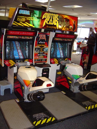
Over at the Boca Bearings Workshop we recently were able to obtain a handful of abandoned arcade games. Once all of them arrived at the shop, Brian and I were pretty eager to find out to what degree all of these games were still functional. I mean who doesn't love some classic arcade games? Once we started looking into some of these machines we realized that there were a lot of wires without any places to be plugged in. After Brian did a little further research it turns out that it was pretty common practice to take the motherboard out of those machines when they were abandoned. This meant that we basically have everything we need except for the software to play a game. One thing we did notice however was that the arcade motorcycles that originally were used for MANX TT Superbike contained three primary input devices, 3 geared potentiometers. With the help of an Arduino we figured we could turn that bike into a controller that would make you feel a little more immersed while driving your R/C car.
Testing the Potentiometers:


So on this machine there is a potentiometer to read the tilt of the bike, how far the break is pulled in, and how far the throttle has been turned. In order to test these devices I powered them with the 5 volt output from the Arduino, connected the ground pin on each of the potentiometer to the ground on the Arduino, and connected each of the signal pins to one of the analog input pins on the Arduino Uno. All three of the potentiometers can share the same 5v input and ground but each one must be connected to a separate analog input pin.

Code:
//Declare variables
int bikeTilt;
int throttle;
int handBreak;
void setup() {
Serial.begin(9600); //Select Baud Rate
}
void loop() {
//Read Pots
bikeTilt = analogRead(A0);
throttle = analogRead(A1);
handBreak = analogRead(A2);
//Print and format values
Serial.print("Bike Tilt=");
Serial.print(bikeTilt);
Serial.print(" Throttle=");
Serial.print(throttle);
Serial.print(" HandBreak=")
Serial.println(handBreak); // the println moves to the next line in the serial monitor
}
Interpreting the Results:
Arduino reads analog signals in 10-bit. This means that each variables read in the code above can range in value from 0-1023, which corresponds to the signal of the potentiometer outputting between 0 and 5 Volts. However because of the way they are set up on the bike they could not actually reach their absolute maximum and minimum. So what I did was run the code above to find out the actual maximum and minimum values for each potentiometer on the bike.
Bike Tilt
313-737
Throttle
75-976
Break
0-305
These values will be important later because these are the range of values that I will use to control the R/C car.
Over at the Boca Bearings Workshop we recently were able to obtain a handful of abandoned arcade games. Once all of them arrived at the shop, Brian and I were pretty eager to find out to what degree all of these games were still functional. I mean who doesn't love some classic arcade games? Once we started looking into some of these machines we realized that there were a lot of wires without any places to be plugged in. After Brian did a little further research it turns out that it was pretty common practice to take the motherboard out of those machines when they were abandoned. This meant that we basically have everything we need except for the software to play a game. One thing we did notice however was that the arcade motorcycles that originally were used for MANX TT Superbike contained three primary input devices, 3 geared potentiometers. With the help of an Arduino we figured we could turn that bike into a controller that would make you feel a little more immersed while driving your R/C car.
Testing the Potentiometers:


So on this machine there is a potentiometer to read the tilt of the bike, how far the break is pulled in, and how far the throttle has been turned. In order to test these devices I powered them with the 5 volt output from the Arduino, connected the ground pin on each of the potentiometer to the ground on the Arduino, and connected each of the signal pins to one of the analog input pins on the Arduino Uno. All three of the potentiometers can share the same 5v input and ground but each one must be connected to a separate analog input pin.
Code:
//Declare variables
int bikeTilt;
int throttle;
int handBreak;
void setup() {
Serial.begin(9600); //Select Baud Rate
}
void loop() {
//Read Pots
bikeTilt = analogRead(A0);
throttle = analogRead(A1);
handBreak = analogRead(A2);
//Print and format values
Serial.print("Bike Tilt=");
Serial.print(bikeTilt);
Serial.print(" Throttle=");
Serial.print(throttle);
Serial.print(" HandBreak=")
Serial.println(handBreak); // the println moves to the next line in the serial monitor
}
Interpreting the Results:
Arduino reads analog signals in 10-bit. This means that each variables read in the code above can range in value from 0-1023, which corresponds to the signal of the potentiometer outputting between 0 and 5 Volts. However because of the way they are set up on the bike they could not actually reach their absolute maximum and minimum. So what I did was run the code above to find out the actual maximum and minimum values for each potentiometer on the bike.
Bike Tilt
313-737
Throttle
75-976
Break
0-305
These values will be important later because these are the range of values that I will use to control the R/C car.
Subscribe to:
Posts (Atom)